Increasing Movement Accuracy
The following part of the course will be set on a brief documentation of how the Pose_Callback.mirocode and Odometry_Usage.mirocode. This will then be followed by an example of how these codes can be used to further increase the accurancy of the movement made by the robot.
The codes for the examples below are available in the Week 5 folder on the Blackboard.
Pose_Callback.mirocode
The following code focuses on obtaining the co-ordinates of the MiRo through data that is provided by the simulation world. Thus, this appears to be the most accurate form of measuring the MiRo's position. The following code has the following variable:
pos_x : It returns float to represent the x-axis distance travelled, in meters. This measurement is taken with reference to the set x-axis of the simulation world.
pos_y : It returns float to represent the y-axis distance travelled, in meters. This measurement is taken with reference to the set y-axis of the simulation world.
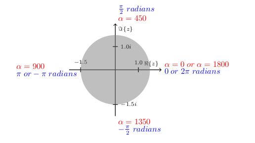
pos_theta: It returns float to represent the angle of the MiRo with reference to a set direction in the world. This is measured in terms of radians and in the case of pose_callback will reference angles similar to that used in the complex plane.
Odometry_Usage.mirocode
The following code focuses on obtaining the co-ordinates of the MiRo through an estimation of each of the wheel's speed and movement. Thus, this appears to be less accurate than using pose_callback.mirocode. The following code has the following variable:
pos_x : It returns float to represent the x-axis distance travelled, in meters. This measurement is taken with reference to the wheels speed and pos_theta.
pos_y : It returns float to represent the y-axis distance travelled, in meters. This measurement is taken with reference to the wheels speed and pos_theta.
pos_theta: It returns float to represent the angle of the MiRo with reference to the initial direction in which the MiRo started. This is measured in terms of radians and will increase on turning anticlockwise and decrease on turning clockwise.
Examples for Improving Accurancy
left_turn_odom.mirocode shows how the odometry data alone could improve the accurancy of the turns. It can be observed that the updates of data in the odometry is delayed in MiRo. Thus, we will be making the MiRo stop earlier than it is required to so that the MiRo is in the desired position. After this, we will be using the wait function for the MiRo to update the correct position of itself.
reset_odom_pose.mirocode shows how the pose data could be used in conjunction with the odom data to reduce discrepancies in data. In the case that the pose data is used, the estimated data will be more inaccurate over time and thus, in this example, we will be replacing the pose data with odom data to improve the accurancy of the pose estimates.
realign_with_callback.mirocode combines all the previous examples and shows how to use MiRo's true pose from the simulator to keep it on a rectilinear grid. You can integrate the presented method into your program and make MiRo auto-correct itself if it has drifted away from the required position. The Blockly code for this example is explained below.
The Program Start section contains variable initialisation, MiRo Pose Subscriber with the pos_cb callback function and the cliff reflex override function.


The main loop consists of two parts: 1. In the first part the program works out where the centre of the cell is, and what is the closest heading the MiRo is facing (N, E, S, W).

- In the second part, an imaginary circle is drawn in the centre of the cell. The radius of the circle represents how far from the centre MiRo is allowed to be. If MiRo's pose is outside the circle, the
ReAlignfunction kicks in and it tries to bring MiRo back to the centre. The function works as follows: - Turn MiRo to face East
- Adjust the X coordinate so that MiRo is in centre along that coordinate
- Turn MiRo to face North
- Adjust the Y coordinate so that MiRo is fully in the centre

- Finally, the original heading (N, E, S, W) is restored
